ATLS 5410 Motor Buffet
Group members: Caitlin Littlejohn, Robyn Marowitz, Eli Skelly, Clayton Hester
Project overview
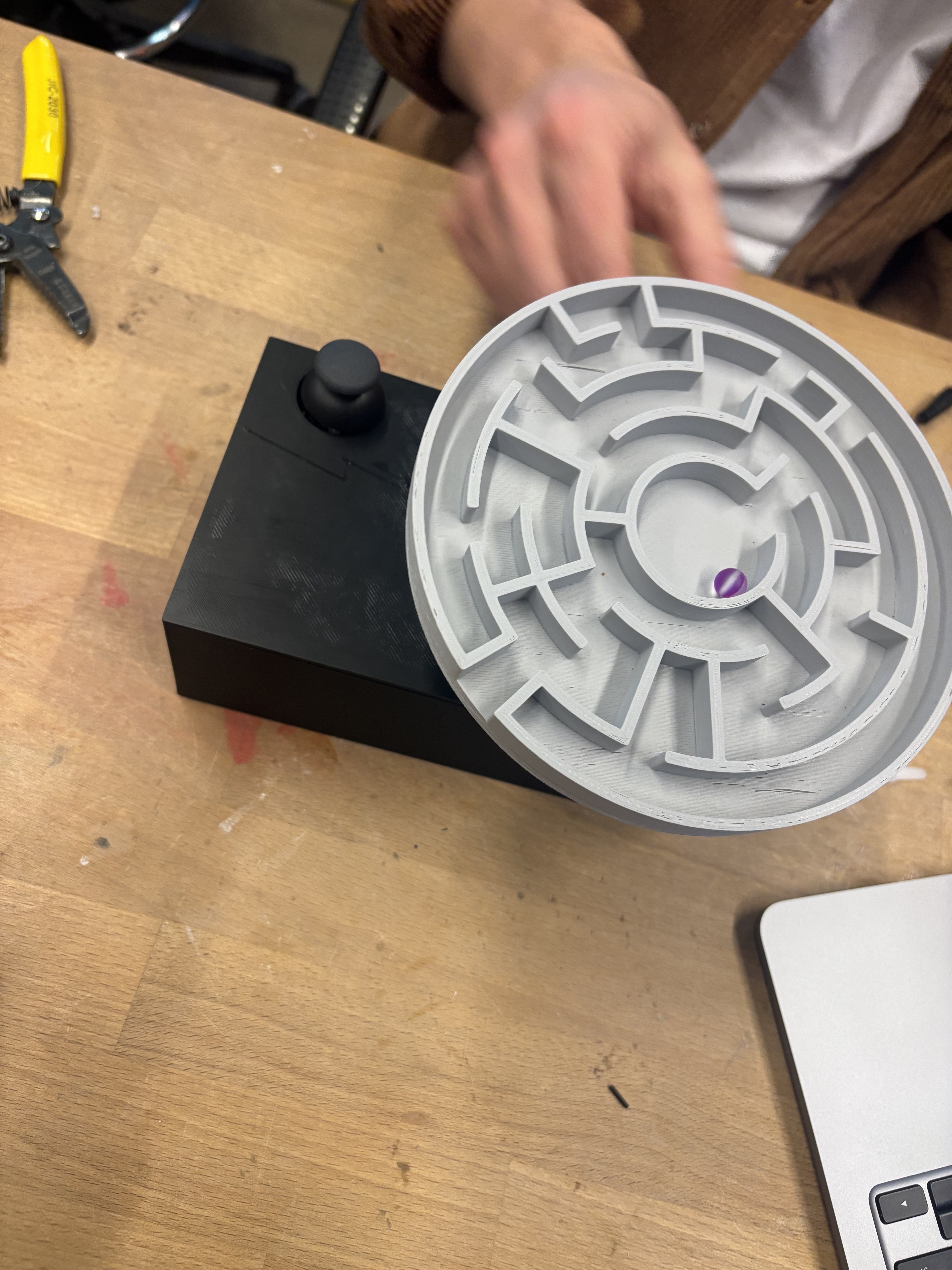
Our idea was to create a maze that is either controlled by either 4 directional buttons or a joystick and use 2 motors in order to have movement in all 4 directions.
Key Considerations
Motor Selection – Servo or Stepper?
We initially explored both options but ultimately chose servo motors, as we found more relevant documentation and examples supporting this approach.Maze Material – Laser-Cut Wood or 3D Printing?
Aesthetically, we liked the idea of carving the maze out of wood. However, considering marble size and motor strength, we decided that 3D printing would be the more practical choice.Power Initially we worked with it plugged into the computer, but since there is a box to contain the wires and system we wanted to be able to hide the power in there. Ultimately a 5V power bank was what worked best for this.
Phase 1: Prototyping and
Getting the motors to work together and be controlled by a joystick.
Phase 2: Testing the system with cardboard.
Phase 3: Putting the pieces together
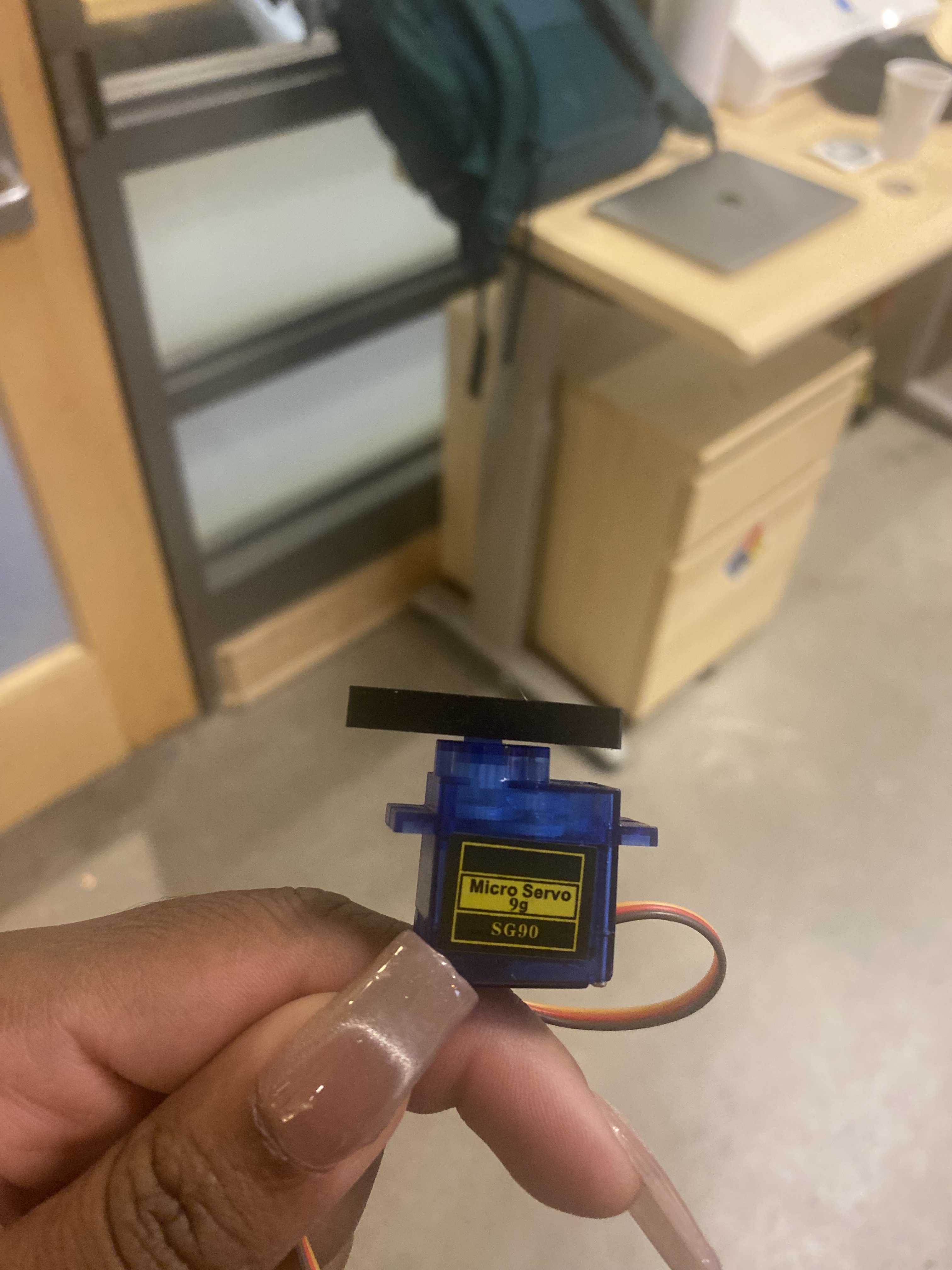
Printing a bracket to attach the motor to the maze and testing it.
Putting it all together.
IDC2: Final Project
Continuing from IDC1
New Components in Iteration 2:
Laser-Cut Enclosure
I designed and laser-cut a clean, modern enclosure to house the Arduino, wiring, and catapult. While some suggested a castle theme, I intentionally chose a minimal aesthetic to better match my design preferences and improve usability.Neopixel Integration
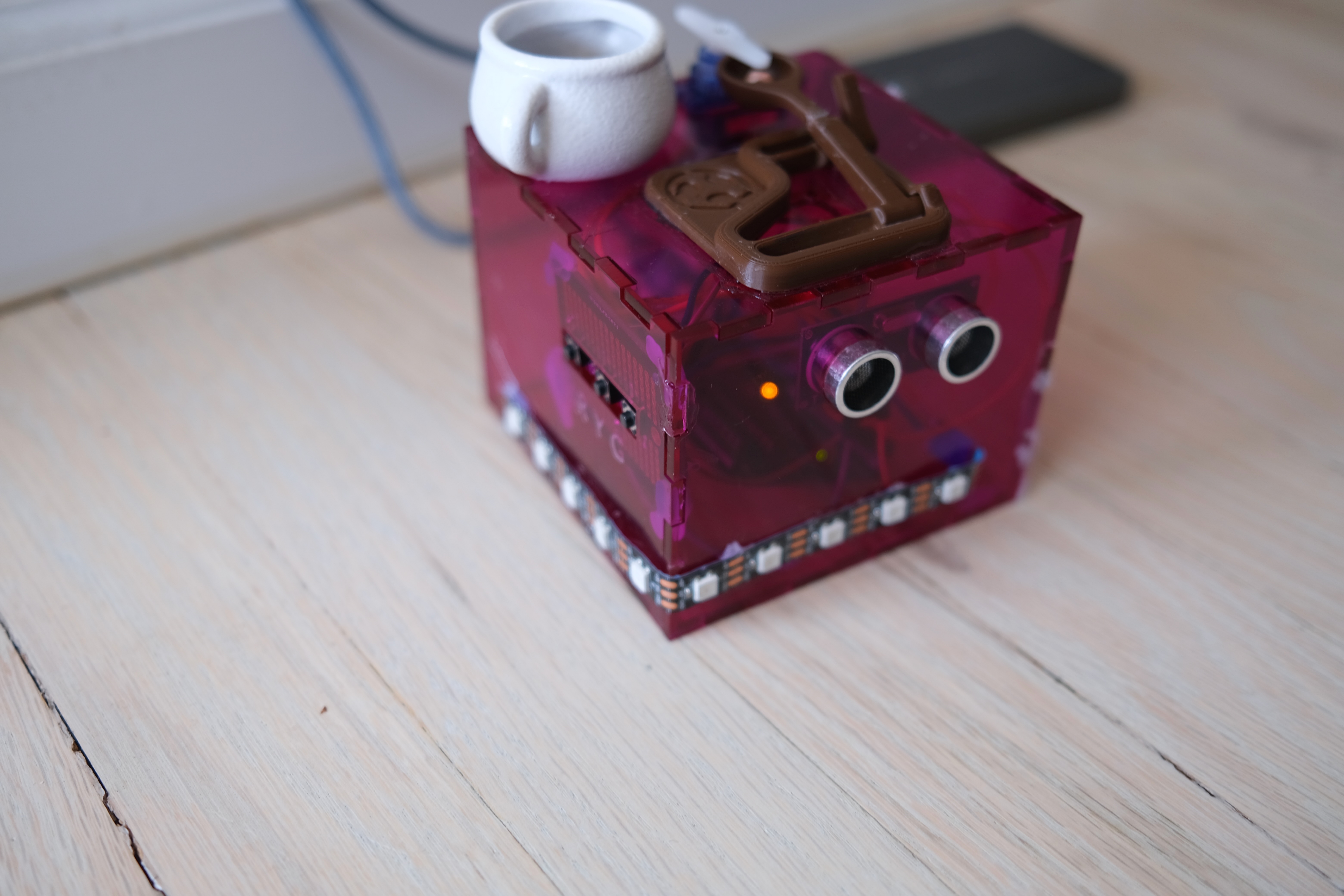
I replaced the individual LEDs with a 13-pixel Neopixel strip for sharper visual feedback and smoother mode transitions.Improved Layout & Wire Management
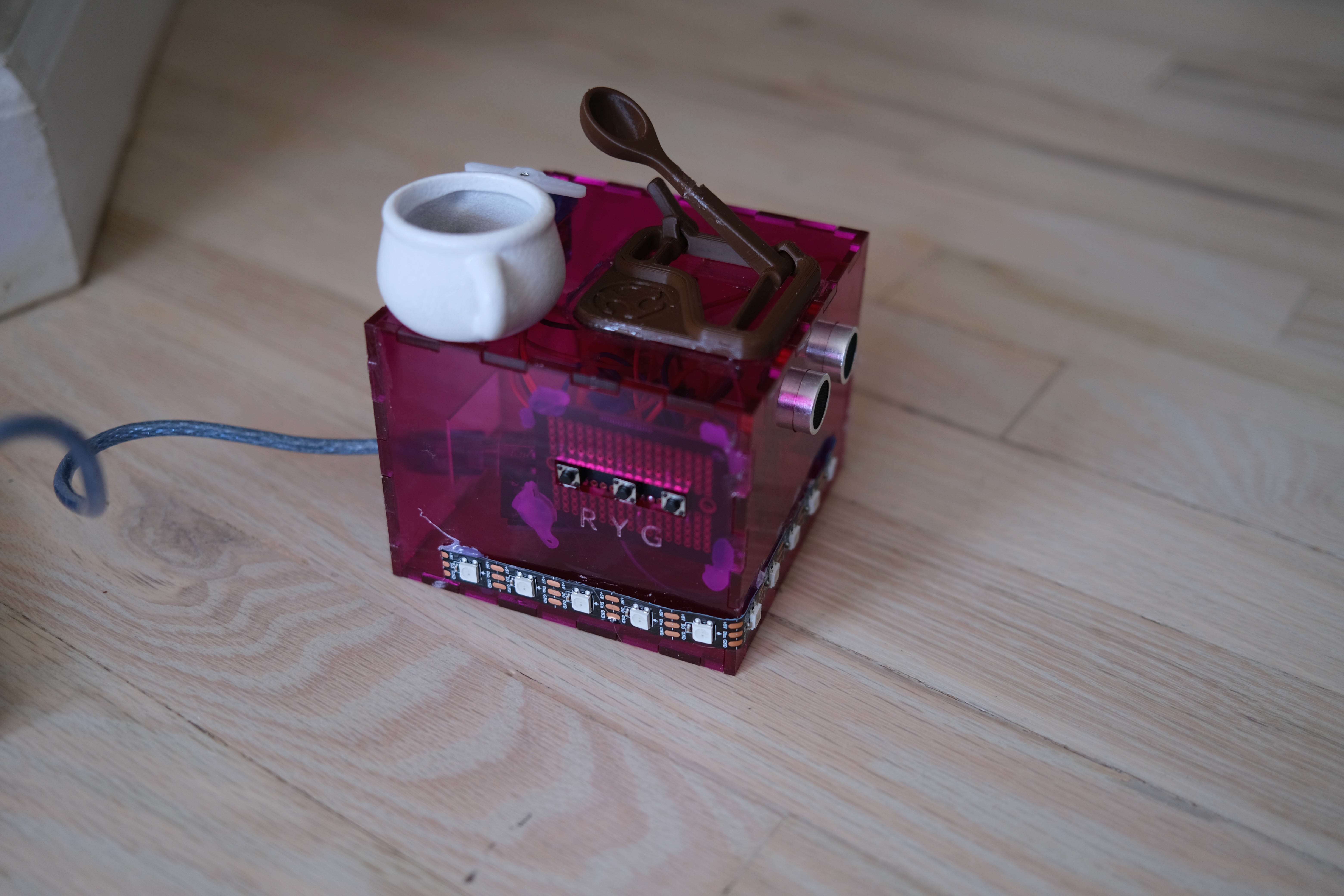
Components were mounted neatly on the enclosure, with soldered buttons on the front panel and the ultrasonic sensor aligned for better detection.
ATLS 5410 IDC1: Independent Design Challenge 1
Solving a Personal Pet Peeve
Pet Peeve:
Working from home, I often get interrupted during meetings or deep work. My desk faces the wall in a shared space, and it’s hard to signal whether I’m free or busy.
Solution:
A light-based availability indicator + proximity sensor + catapult deterrent.
The device uses an ultrasonic sensor to detect approach and changes behavior depending on my selected mode.
Components: - Ultrasonic sensor - Neopixel strip (later version) - Servo motor (to fire the catapult) - Buttons for switching modes - Arduino
Phase 1: Getting the Basics Working
I began by testing individual components:
- Ultrasonic sensor measuring distance
- LEDs lighting up at different proximity thresholds
- Button press logic for switching between modes
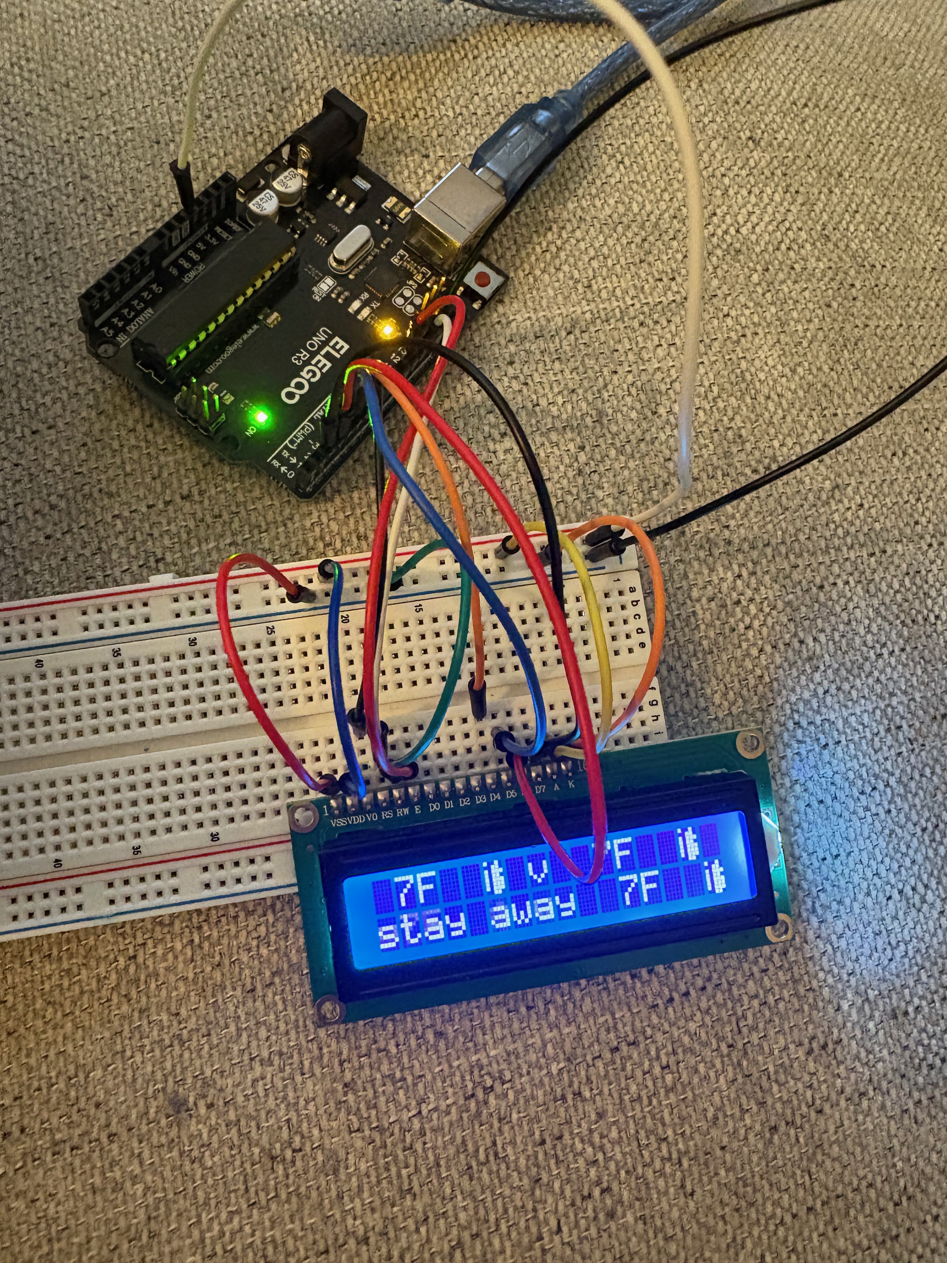
- Brief attempt with an LCD screen (abandoned due to poor legibility and pin limitations)
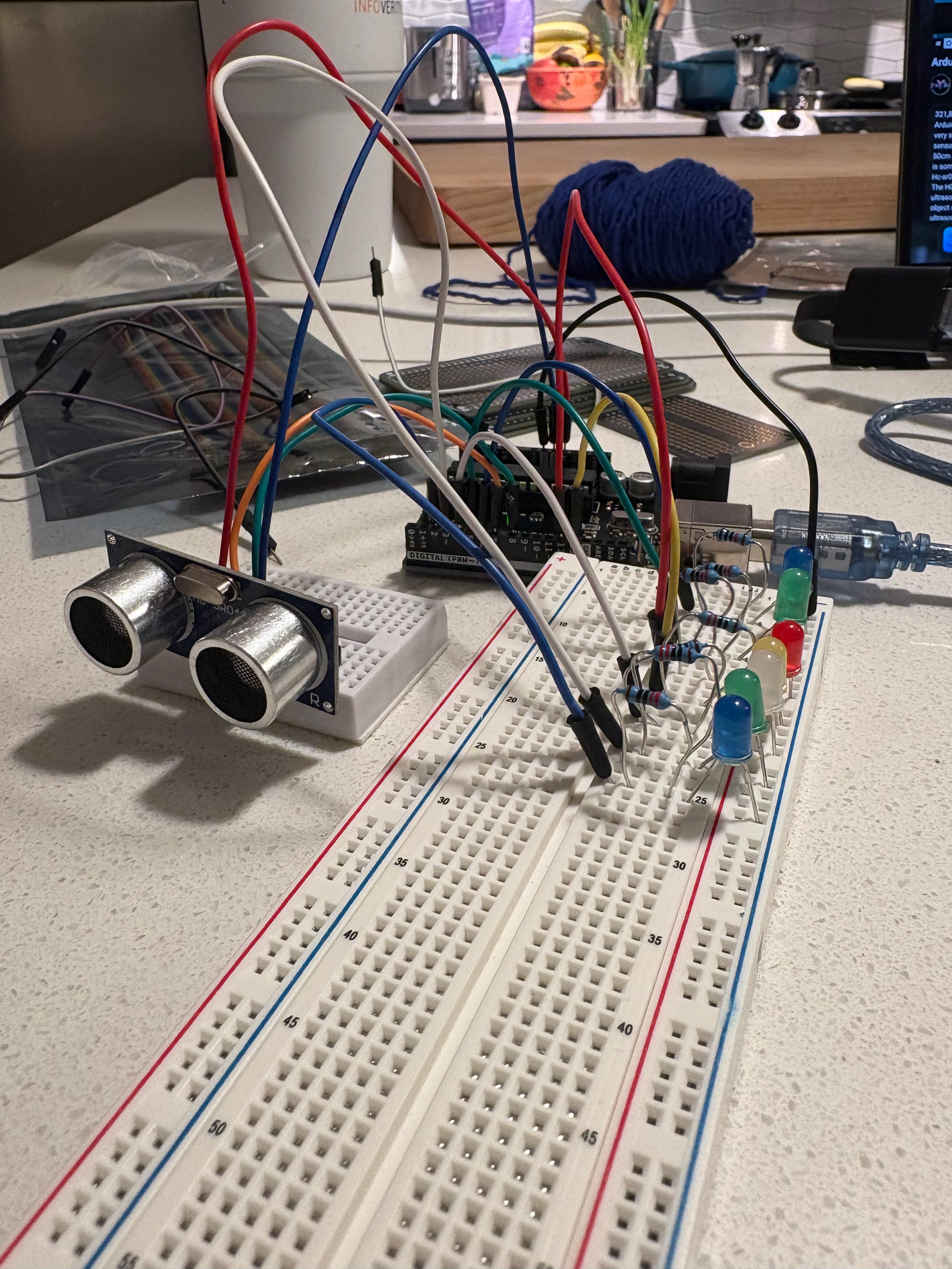
Inspired by Motor Buffet, I leveled up the project by adding a servo-controlled mini catapult to act when someone approaches in “Do Not Disturb” mode.
Phase 2: Adding the Catapult & Finalizing Code
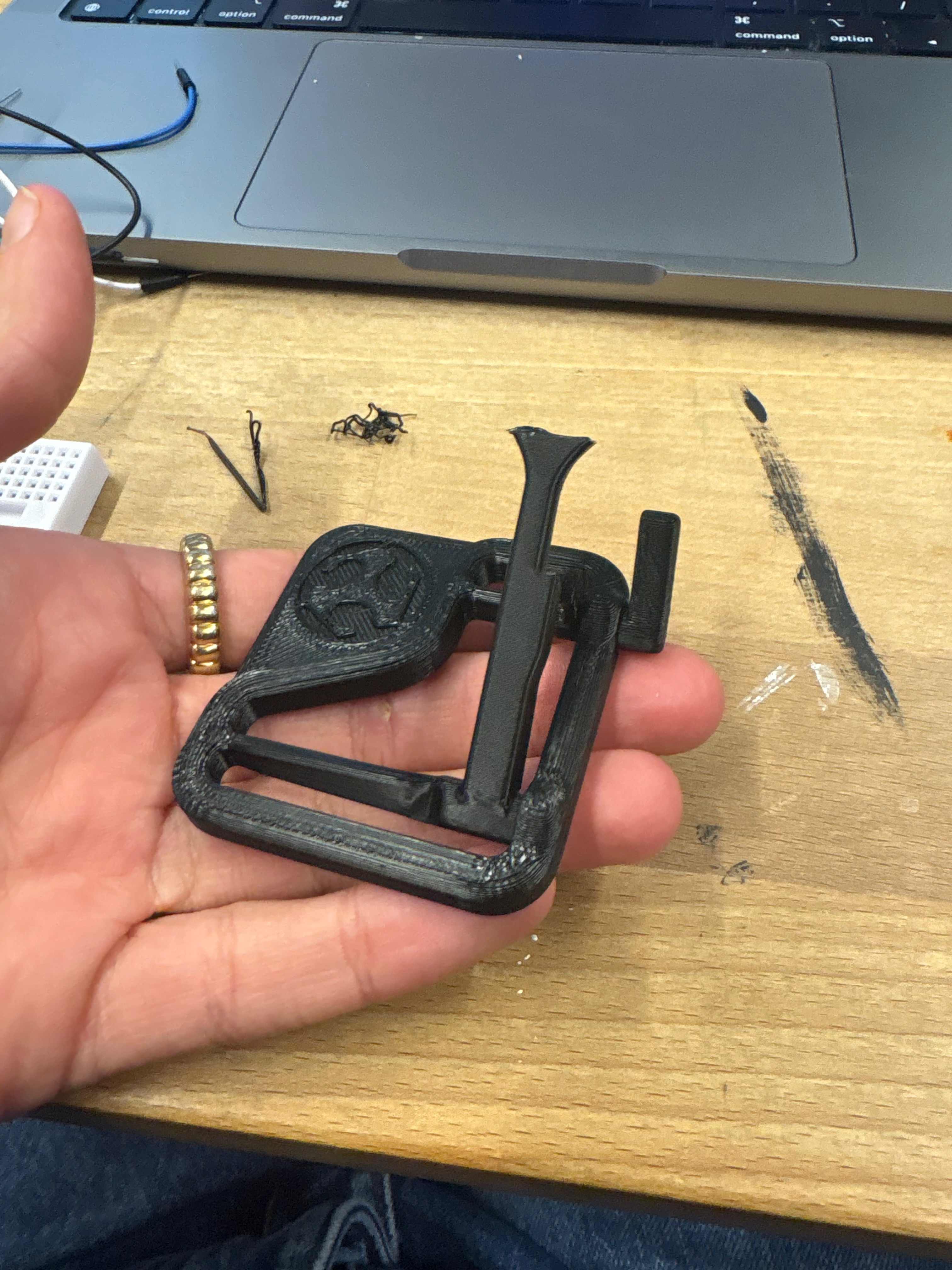
I 3D printed the catapult, requiring a few iterations to get the mechanism tuned.
System Behavior:
- 🔴 Red Mode: Red light; fires catapult if someone gets within 12 inches
- 🟡 Yellow Mode: Yellow light; blinking increases as someone approaches
- 🟢 Green Mode: Green light; always on, no action taken
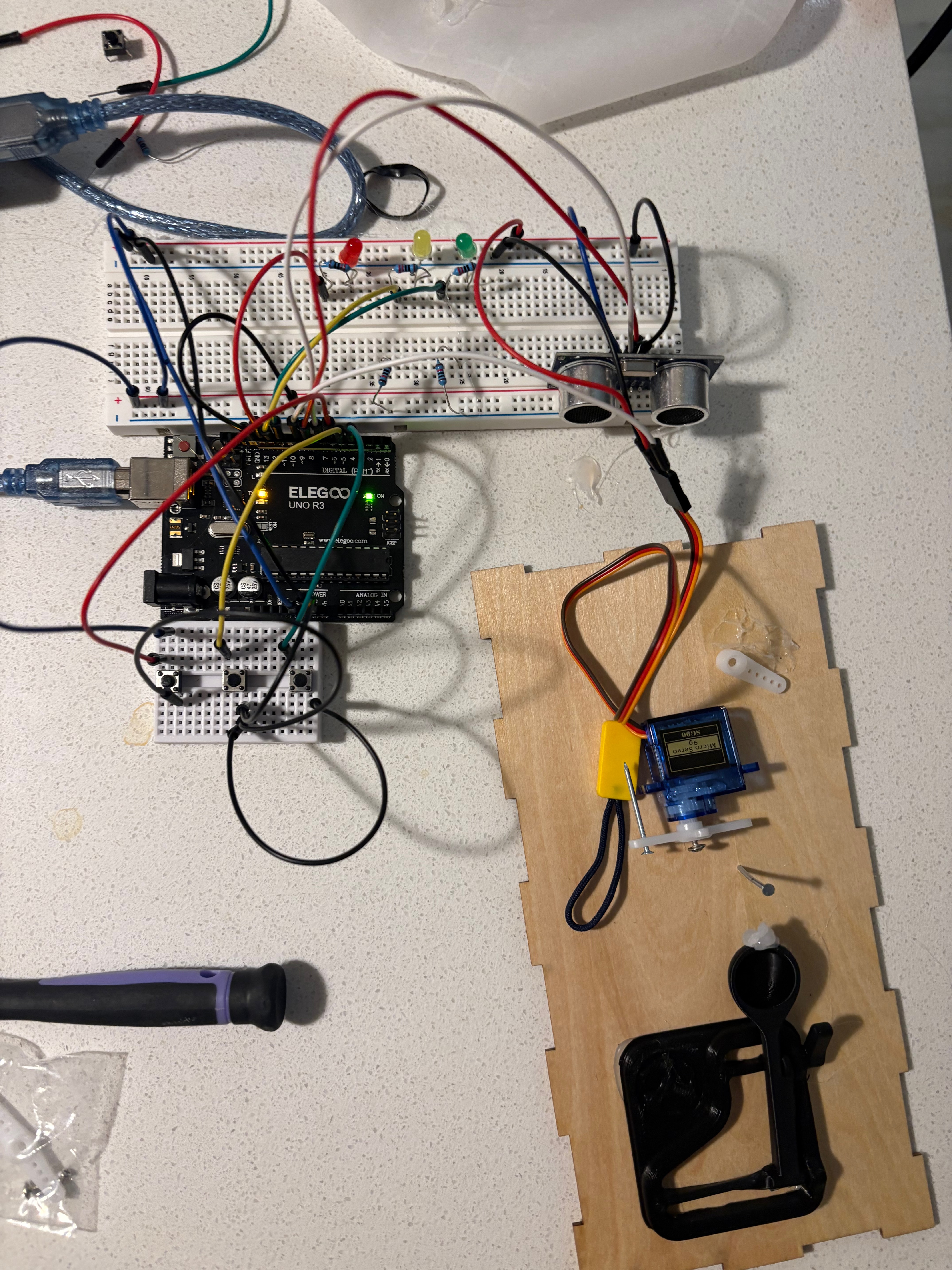
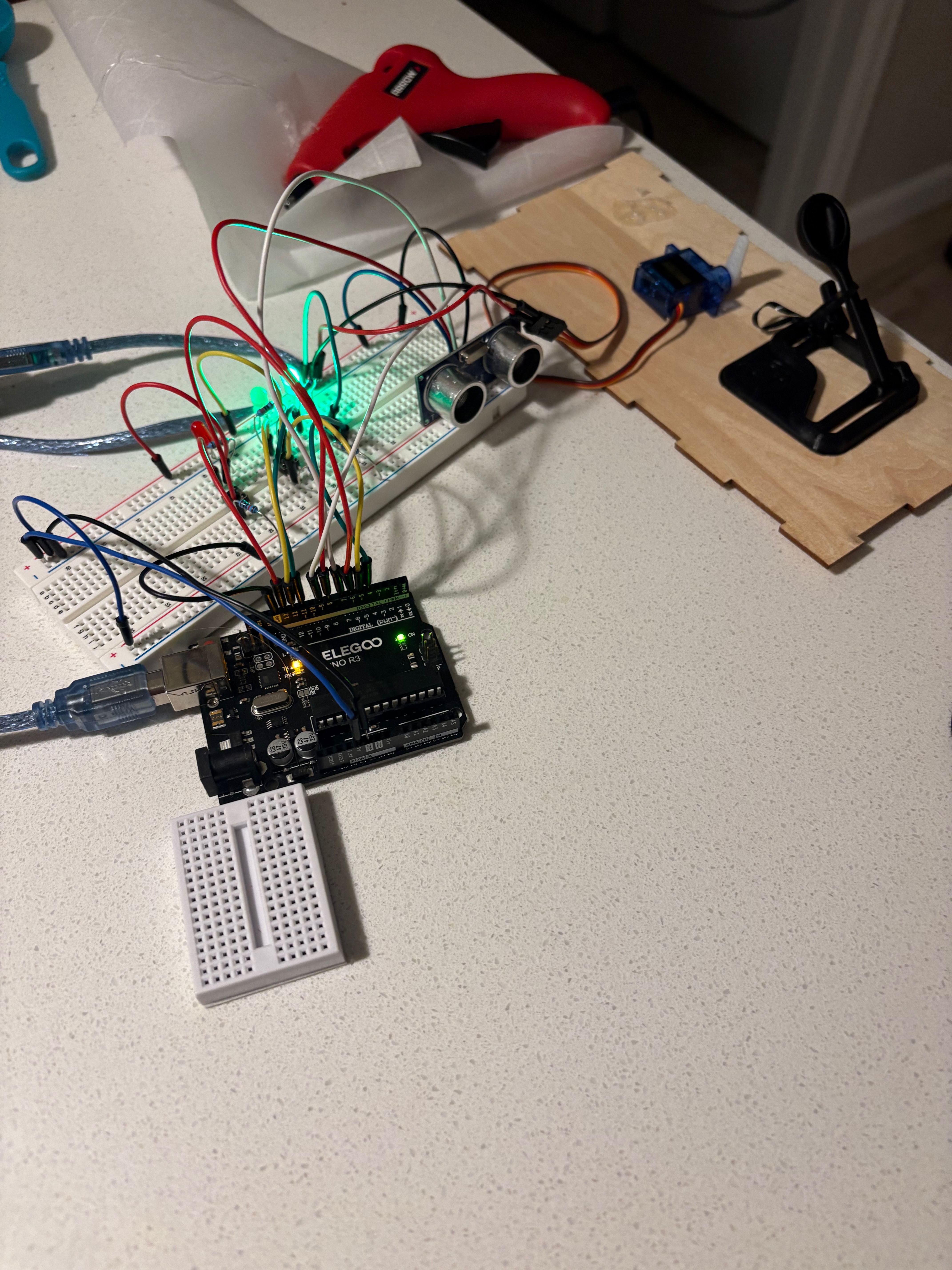
The servo logic was synced with proximity thresholds, and LEDs reflected current mode.
Phase 3: Improving Aesthetics & Usability
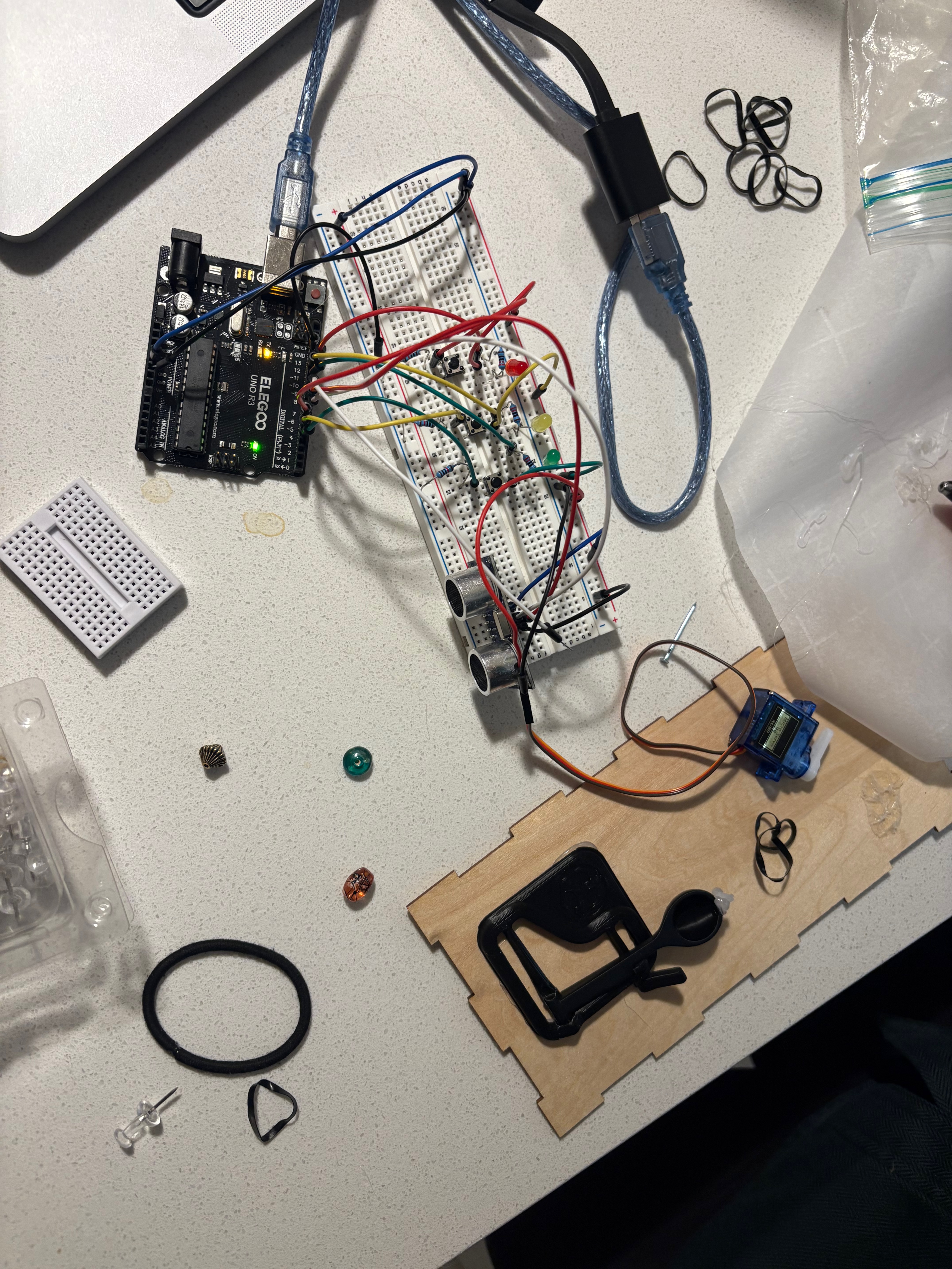
The wiring became messy with so many components, so I split off the buttons onto a second breadboard…
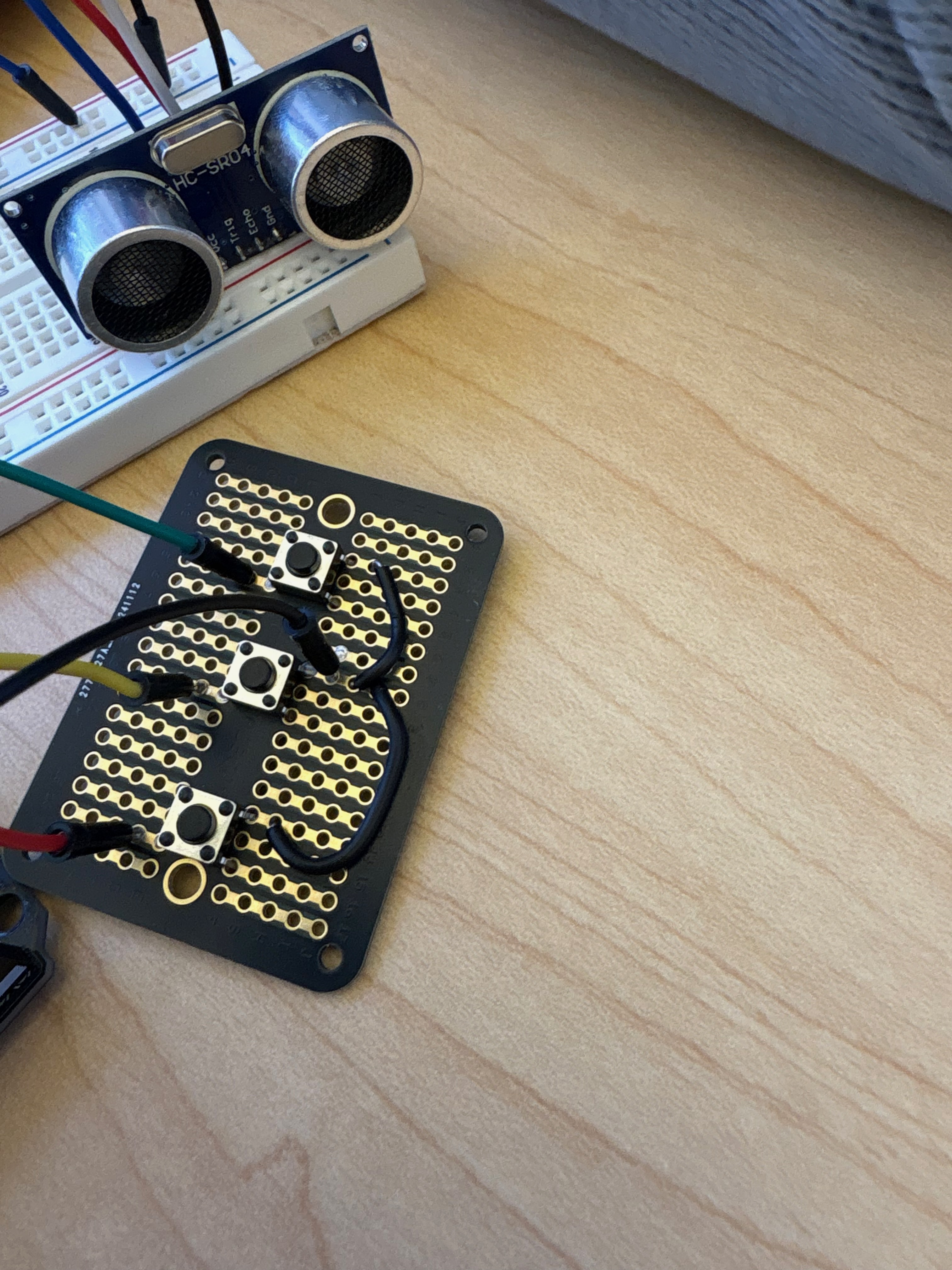
Then I soldered the key components and mounted the buttons more securely for usability.
Phase 4: Redesign Goals & Feedback
After a meeting with Zack, I refocused on:
Better lighting with Neopixels
A more polished enclosure
Exploring (but not fully implementing) a stepper-based auto-reset
I replaced the 3 LEDs with a Neopixel strip to control color and blinking intensity dynamically, linked to proximity.
Phase 5: Final Assembly & Polishing
This phase brought everything together:
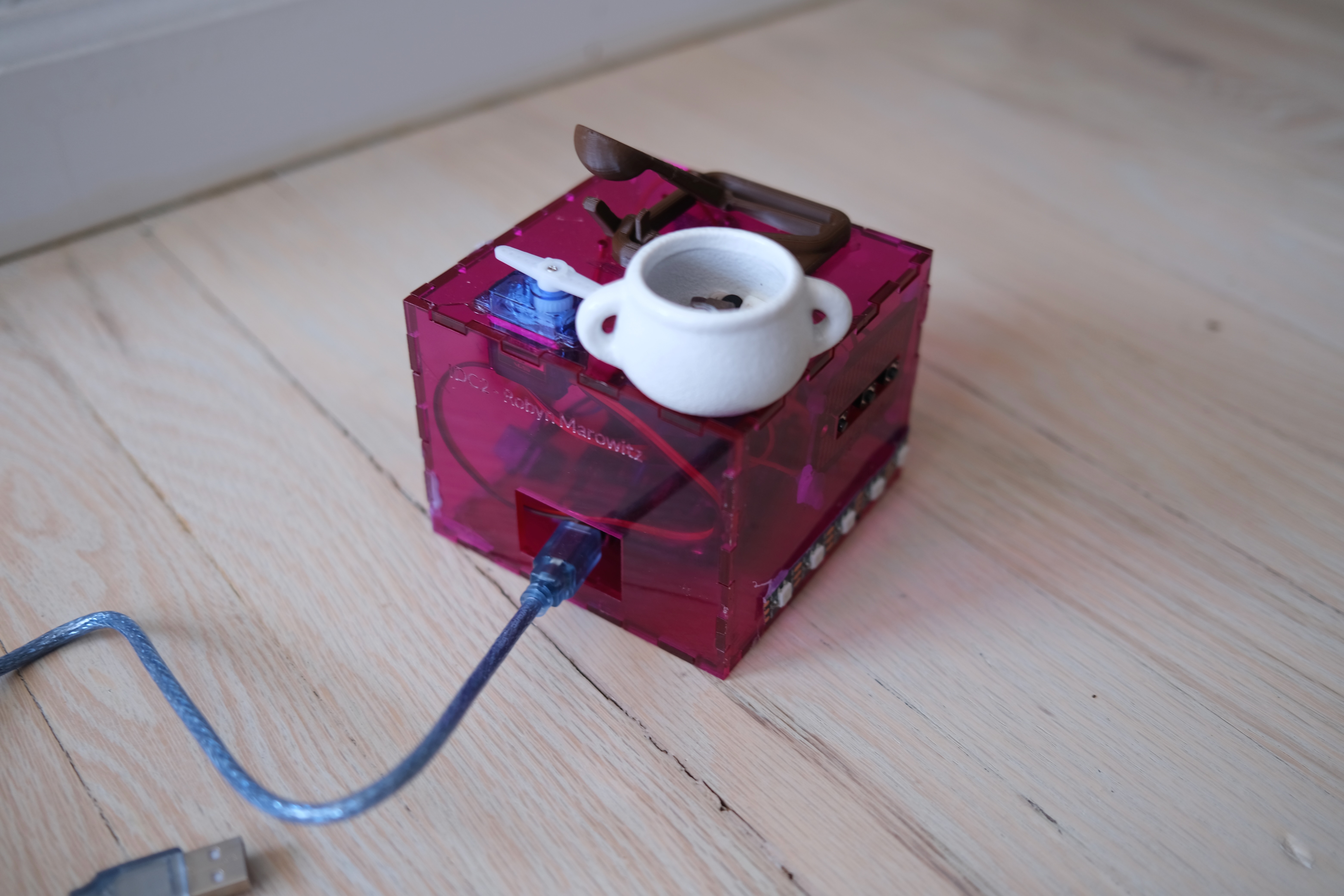
🧰 Laser-cut acrylic enclosure
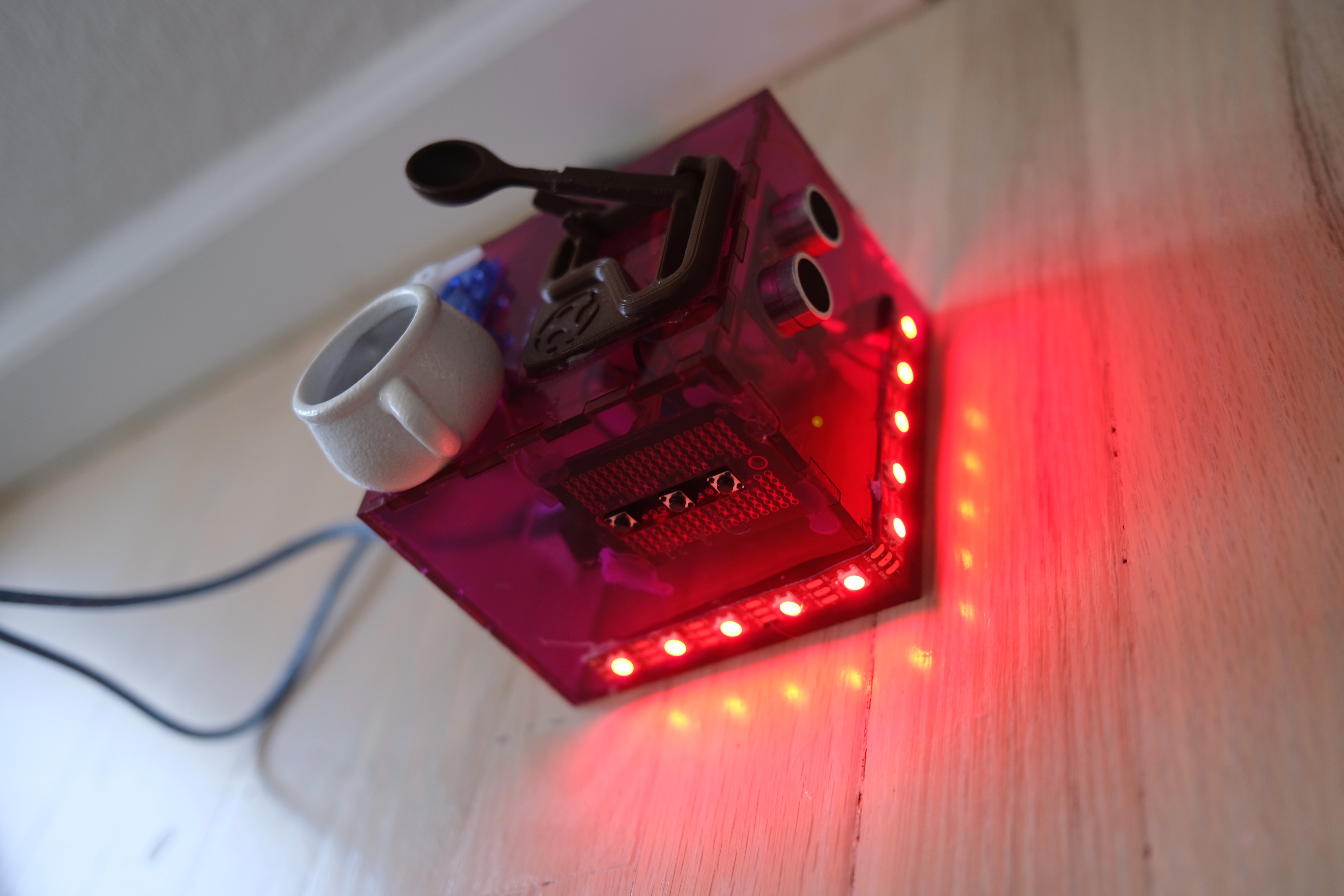
A clean, structured box designed to contain all components with mounted buttons and an aligned sensor.💡 Neopixel visual feedback
Each mode clearly signals status:- 🔴 Red Mode →
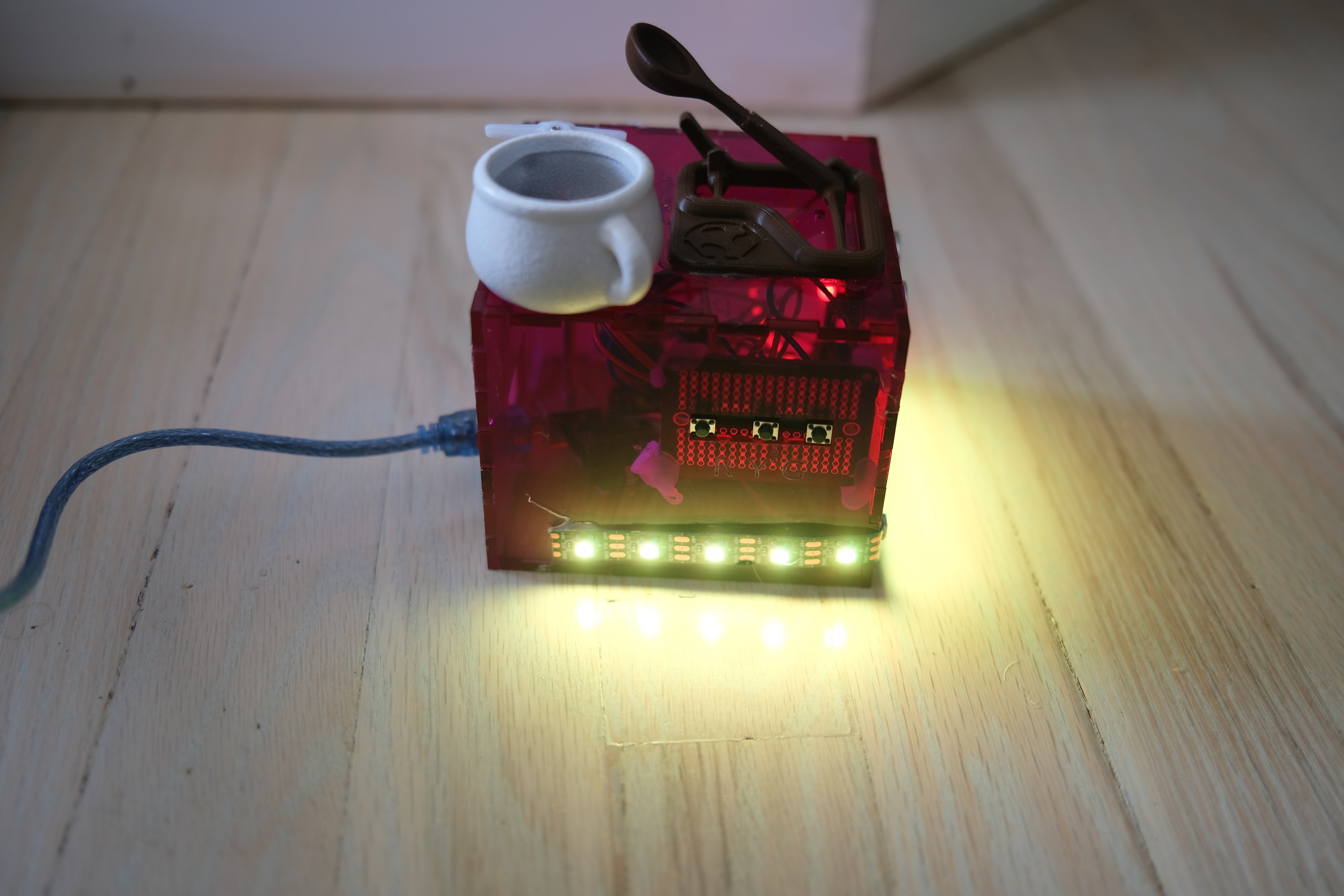
- 🟡 Yellow Mode →
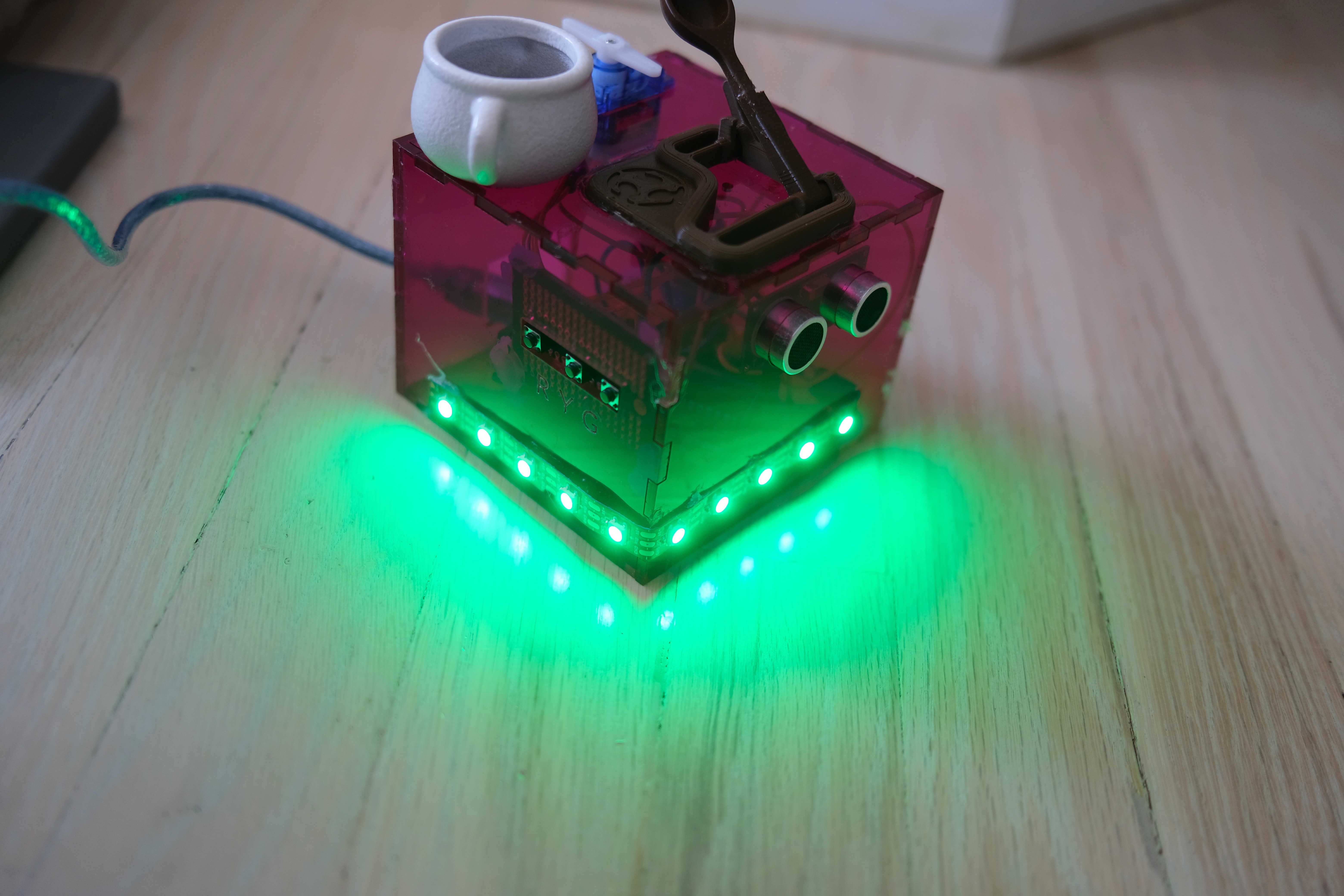
- 🟢 Green Mode →
- 🔴 Red Mode →
🎯 Final function demo (all modes)
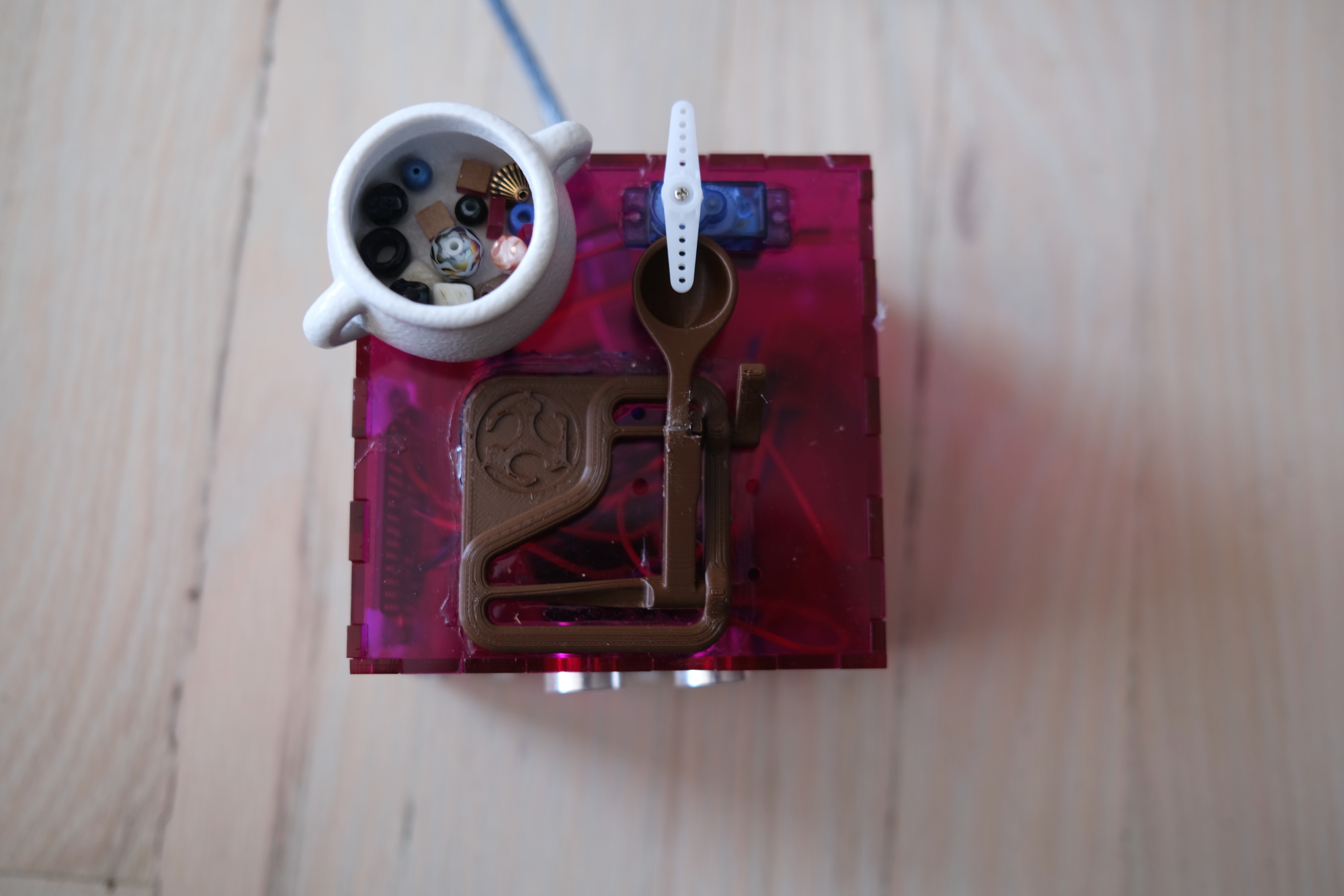
🧠 Ammo tray + soldered layout
A small dish holds extra projectiles. All components are soldered and/or anchored in place for durability. Discovering E6000 was a life saver in this project.
Future Work
One feature I explored but could not fully complete was automatically pulling the catapult arm back into position. I experimented with a 28BYJ-48 stepper motor attached to a string, but wasn’t able to generate enough torque for consistent resets.
For future iterations, I would:
Upgrade to a more powerful stepper motor (e.g., NEMA 17)
Redesign the reset linkage to require less force
Summary
This project turned into a fun blend of real-world productivity signaling and a slightly absurd medieval defense system—exactly the creative combination I was aiming for. This project began as a serious solution to an everyday annoyance—and ended up as a playful, well-engineered physical computing system. The final product reliably signals my availability and adds a bit of (harmless) chaos when boundaries are crossed.
Unused IDC ideas
Automated row counter for knitting
Project Overview
An Automated Row Counter is a small device that helps knitters track their rows and stitches automatically, reducing the need for manual counting. The device could be attached to the knitting needles or worn like a ring, and it would detect movement (knitting motion) or rely on manual input (a small button press per row). The count would be displayed on an LED screen or a mobile app. Recently I was knitting a blanket that had a 17 row pattern and it felt impossible to keep track sometimes and I had to start over twice then just accepted that the pattern would not be perfect.
Design Considerations
1. Input Mechanism (How to Detect Row Progress)
- Button-Based: A small button that you press at the end of each row.
- Motion Sensor (Accelerometer/Gyro): Detects wrist or needle movement and counts stitches automatically.
- Magnetic Switch (Reed Switch): Detects when the needle passes a fixed point using a tiny magnet. - Conductive Yarn Sensors: Detects electrical contact between knitting needles at the start of each row.
2. Display/Feedback Mechanism
- Small OLED Screen: Shows row count and updates in real time.
- LED Indicator: Blinks a specific color after a set number of rows (e.g., every 10 rows).
- Vibration Feedback: Provides haptic feedback when you reach a milestone.
- Mobile App or Web Interface: Connects via Bluetooth to track progress.
3. Power & Enclosure
- Battery-Powered (Rechargeable or Coin Cell): Needs to be compact and long-lasting.
- Enclosure: 3D printed or laser-cut case to attach to knitting needles, clip onto fabric, or be worn like a ring.
Additional Features & Enhancements
- Undo Option: If you make a mistake, a small button lets you decrease the row count.
- Customizable Alerts: Set alerts for increases/decreases, color changes, or pattern repeats.
- Data Logging & Connectivity: Send data to a smartphone app for tracking progress over time. stretch
- Pattern Assistance: Store knitting patterns and provide step reminders.
Multiple Counters: Track multiple projects at once with different row counters.
Technical Breakdown
- Microcontroller: Arduino (Nano, ESP32, or similar) to handle inputs and processing.
- Sensor Options:
- Button for manual row counting.
- Accelerometer or gyroscope for motion-based detection.
- Magnetic reed switch for passive tracking.
- Display: OLED screen or LED indicators.
- Power Source: Rechargeable battery with efficient power management.
- Communication (Optional): Bluetooth for mobile app connectivity.
- Enclosure: Custom 3D-printed or laser-cut case for ease of use.
Next Steps
- Prototype Input Detection: Test a motion sensor vs. button input.
- Consider if this works in the round or just on standard needles.
- Determine Display Needs: Simple LED feedback vs. OLED display.
- Build a Basic Prototype: Get an Arduino counting rows based on input.
- Design the Enclosure: Think about how to attach the device in a way that’s comfortable for knitters.
Idea 2: Meal Decider
Pet Peeve: Struggling to decide what to eat for lunch or dinner.
Solution:
A physical meal suggestion device that helps pick a meal based on my input and sends a recipe from a list of pre-selected options to my phone via bluetooth. I want te options to be pre-selected since I have some allergies/dietary restrictions and want them to be things I would actuallty want to make.
How it Works:
1. Press a button or turn a dial to generate a random meal suggestion.
2. The LCD screen or LED display shows the meal idea (Tacos, Curry, etc) 3. Bluetooth sends a recipe link to my phone for the selected meal.
4. (Optional) A second button allows for a re-roll if I don’t like the first option.
Possible Components:
- Push button or rotary dial (to select a meal).
- LCD screen or LED matrix (to display meal suggestions).
- HC-05 or HC-06 Bluetooth module (to send recipe links to my phone).
- Arduino (to handle meal selection, display, and Bluetooth connection).
- Pre-set meal list with corresponding recipe URLs.
Challenges & Considerations:
- Ensuring Bluetooth pairing is smooth and simple.
- How to encorporate a pre-set list of meal ideas and recipe links.
Idea 3: Euchre Scorekeeper
Pet Peeve: Keeping score during Euchre can be tricky, especially when drinking, chatting, or multitasking. People forget to update the score, and sometimes there’s debate about what it should be.
Solution A simple Euchre Scorekeeper that tracks the game’s progress with minimal effort so players can focus on having fun.
Features
- Single-button simplicity: Each team has one button—click it the correct number of times to record points.
- Handles Euchre-specific scoring rules:
- 1 click = 1 point (standard round win).
- 2 clicks = 2 points (team wins all 5 tricks or Euchres opponents).
- 4 clicks = 4 points (someone goes alone and wins).
- Visible score display: A bright LED or LCD screen shows the current score at all times.
- Drinking-Friendly Mode: Can provide random demands like“Time for a cheers!”.
- Auto-reset: When a team reaches 10 points, the device flashes the winner’s name and resets automatically.
How It Works 1. Each team has one button.
2. The button is pressed once per point earned (1, 2, or 4 times).
3. The LED display updates the score in real time.
4. When a team reaches 10 points, the game announces the winner and resets automatically.
Components
- 2 push buttons (one for each team).
- LED display or LCD screen to show the score.
- Arduino (to process scoring logic).
- Buzzer or LED flash when a team scores.
Challenges & Considerations
- Avoiding accidental button presses - Ensuring points are counted correctly (a short delay between clicks to prevent double-counting).
- Should there be an undo option?